Fault Condition: The Electronic Malfunction Lamp (EML) will illuminate when the Fuel Pressure (FP) Sensor signal line voltage is less than 0.3 volts or greater than 4.75 volts. Ifthe signal line voltage returns to between 0.3 volts and 4.75 volts the fault will become inactive.
Possible repairs:
Turn the ignition key OFF first.
1) Disconnect Engine Management System (EMS) Module connectors B. Check for continuity between Fuel Pressure (FP) Sensor harness connector pin 2 (signal line) and a good ground. If continuity exists, locate and repair the short circuit to ground.
2) Disconnect Engine Management System (EMS) Module connector B. Check for continuity between Fuel Pressure (FP) Sensor harness connector pin 1 (reference voltage line) and EMS Module harness connector B pin 17.
If there is NO continuity, repair the open in the harness reference voltage line.
3) Disconnect the Fuel Pressure (FP) Sensor. Disconnect Engine Management System (EMS) Module connectors A and B. Check for continuity between EMS Module harness connector B pin 16 (signal line) and all other pins in EMS Module harness connectors A and B. Visually check EMS Module connector B pin 16 for a short circuit. If continuity exists or if there is a visual short, repair the short circuit to the signal line. If there is NO continuity or visual short, replace the EMS Module.
4) Disconnect the Fuel Pressure (FP) Sensor and the Engine Management System (EMS) Module connector B. Check for continuity between Fuel Pressure (FP) Sensor harness connector pin 2 (signal line) and EMS Module harness connector B pin 16. If there is NO continuity, repair the open in the harness signal line.
5) Disconnect the Fuel Pressure (FP) Sensor and the Engine Management System (EMS) Module connectors A and B. Check for continuity between EMS Module harness connector B pin 17 (reference voltage line) and all other pins in EMS Module harness connectors A and B. Visually check EMS Module connector B pin 17 for a short circuit. If continuity exists or if there is a visual short, repair the short circuit to the reference voltage line.
If there is NO continuity, visual short or loose, corroded and damaged terminals, replace the EMS Module.
6) Disconnect Engine Management System (EMS) Module connectors A and B. Disconnect the Fuel Pressure (FP) Sensor. Check for continuity between EMS Module harness connector B pin 17 (reference voltage line) and all other pins in EMS Module harness connectors A and B. Visually check EMS Module connector B pin 17 for a short circuit. If continuity exists or if there is a visual short, repair the short circuit to the reference voltage line.
If there is NO continuity or visual short circuit, replace the EMS Module.
7) Visually inspect both sides of the Fuel Pressure Sensor connector for a repairable open. If any of the pins feel loose or an open is found, replace the Fuel Pressure (FP) Sensor.
8) Disconnect Engine Management System (EMS) Module connectors A and B. Disconnect the Fuel Pressure (FP) Sensor. Check for continuity between EMS Module harness connector B pin 18 (ground line) and all other pins in EMS Module harness connectors A and B. Visually check EMS Module connector B pin 18 for a short circuit. If continuity exists or if there is a visual short circuit, repair the short to the return line. If there is NO continuity or visual short circuit, replace the EMS Module.
9) Visually inspect both sides of EMS Module connector B pin 11 for a repairable open in the signal line. If a repairable open is found, repair or replace EMS Module harness connector B.
10) Remove the Fuel Pressure (FP) Sensor. Connect the Fuel Pressure (FP) Sensor to a regulated air supply with an accurate pressure gauge. Connect a jumper wire between Fuel Pressure (FP) Sensor pin 1 and pin 1 on the
sensor harness connector. Connect a jumper wire between Fuel Pressure (FP) Sensor pin 4 and a good ground. Turn the ignition key ON. Measure the voltage between Fuel Pressure (FP) Sensor pin 2 and a good ground at
various pressures between 0 psi and 101.5 psi.
11) Visually inspect both sides of EMS Module connector B pin 18 for a repairable open in the ground line. If a repairable open is found, repair or replace EMS Module harness connector B. If the pin is making good contact, replace the EMS Module.


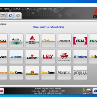
 AGCO
AGCO ALLISON
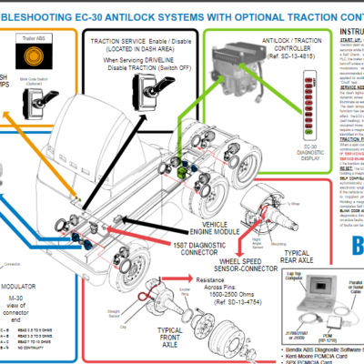
 BENDIX
 BOBCAT
 CAT
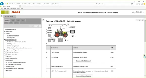
CAT CLAAS
CLAAS CNH
CNH DAF
DAF DETROIT
 EATON
EATON FREIGHTLINER
 HINO
HINO HITACHI
 ISUZU
ISUZU JCB
JCB JOHN DEERE
 JPRO
JPRO MAGIC TUNER
 MAN
MAN Navistar
 PACCAR
 PERKINS
 PF DIAGNOSE
 PSI POWERLINK
 RENAULT
 SCANIA
 THERMO KING
 UD NISSAN
 VOLVO
VOLVO WABCO
WABCO ZF TESTMAN
 BELL
BELL BENDIX
 BOBCAT
 CARRIE
 DAF
DAF DETROIT
 EATON
EATON FUSO
FUSO MACK
MACK
 Cumminz
 ISB4.5 CM2150
 All Engines (2017 Emissions)
 PACCAR




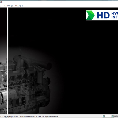
![The DOOSAN EDOCTOR CONSTRUCTION FULL 2.3.5.8 [2023.06] is a cutting-edge diagnostic software for heavy machinery. Released in 2023, it offers advanced tools for troubleshooting engine issues in various construction equipment. This software enhances operational efficiency by providing detailed diagnostics and real-time support. It is compatible with multiple brands and supports remote installation through TeamViewer, ensuring seamless usability for technicians.](https://ecmtrucks.com/wp-content/uploads/2024/08/88-400x400.png)

Reviews
Clear filtersThere are no reviews yet.